Sunday, February 06, 2011

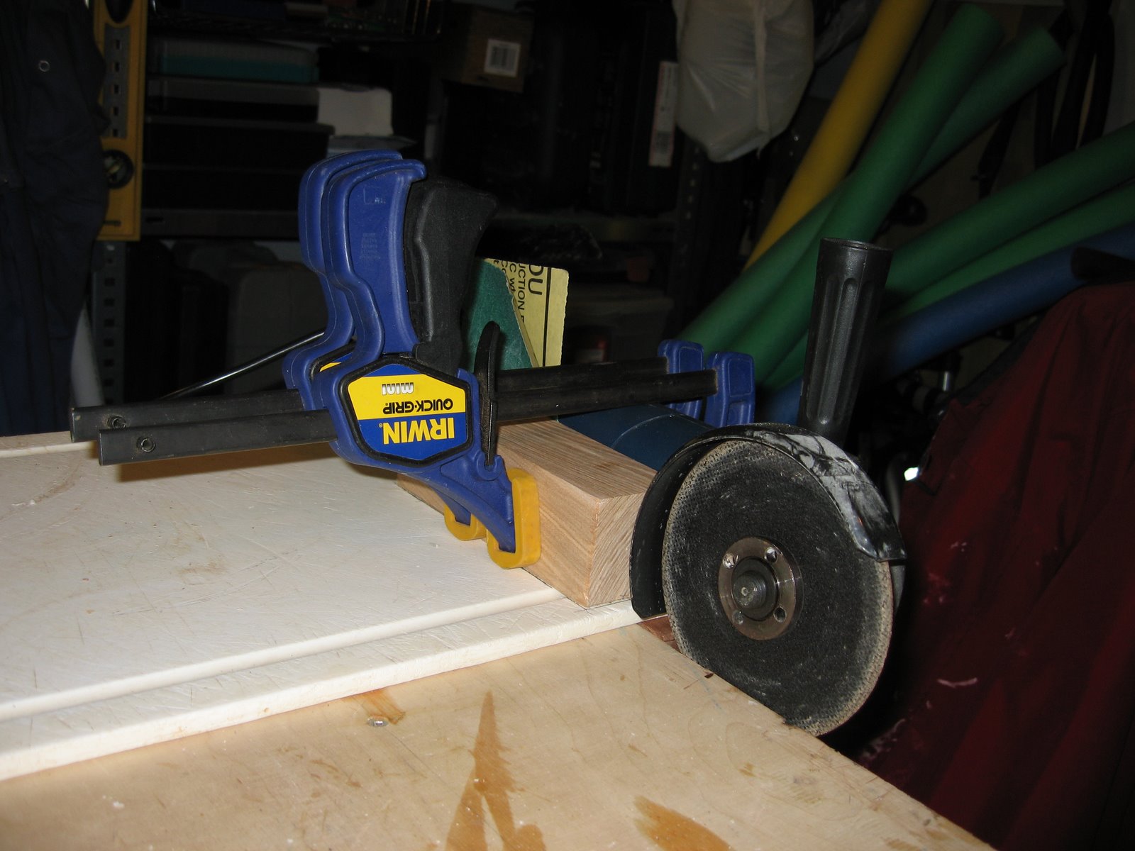
A simple cut off saw.


Since I don't really need a metal cut off saw all that often, and I have little room for more tools, I cobbled this together. It's just an angle grinder, and a sled. The sled is constrained by runners, so it moves in a straight line.
The Cutting blade is close enough to square to the table for my purposes.

I tried it out by cutting a hollow steel rod at 45 degrees, and then flipping the parts to join them at 90 degrees. It works just fine.

Yes, that is an old bread board.
Posted by Picasa

Sunday, January 23, 2011

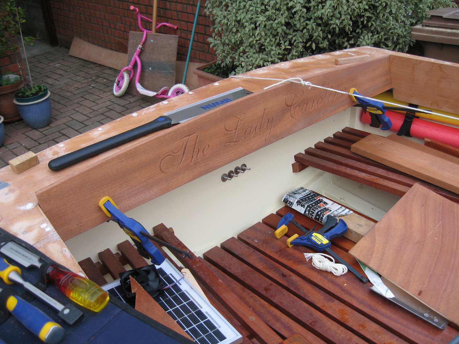
The Coamings


So I have started working on the Coamings. I can't claim the carving, I tried some smaller work, and it came out fine, but my practice pieces on larger letters were less consistent. So I sent the coaming to Wood Graphics Ireland who did a nice job.


Of course cutting to fit is a job and a half, since you have compound angles and a curve.


But I need to figure out how to join the ends

Sunday, January 16, 2011

Making More Cleats


You can see the blanks here, the curves are cut on a drill stand with a 20mm Forstner bit. ThenI cut the horns before putting a 1/12 slope on each side. Of course, with my new found confidence, I made the base a little too short, but since they are for a 14' sailing dinghy, they should cope ok.


A rasp and a belt sander clamped upside down on a table with an 80 grit belt will do most of the shaping, and then you cut strips of a sanding belt and do the insides of the curve shoe shiner fashion.
Posted by Picasa

Friday, January 14, 2011

Making Cleats


Ok, so it took about 2 hours to make this, and it turned out a little thin on top. But since it's only going to hold the centerboard pennant, it should be fine.

Now that I have an Idea what I am doing, I think I will be able to churn one out in about 15 minutes.


  • A simple guide on the drill press means I can cut the holes for the curves without carefully measuring each block.
  • The order of cutting on the bandsaw is all important when some of the cuts are not at 90 degrees.
  • It's a lot easier to round the end of the cleat on a sander than on a bandsaw.
  • When you are joining a curve (20mm drill bit) and a straight line, don't try for a perfect tangent, cut inside the tangent, tidy up with sandpaper or a file.


It is still hard to explain why I spent all that time, instead of just buying a half a dozen nylon ones. At least it's hard to explain to some people.

Monday, January 03, 2011

The Drill bit

 
Posted by Picasa

One home made brazed drill bit. Not pretty, but it worked just fine.

Sunday, January 02, 2011

Tool Maker

All I needed was a 3/8" drill bit, about 2" long, and with a 1/4" hex fitting on the end. You see I could not get a drill in to the gap, so I'd have to use a ratchet with a hex drive.

No problem, I have lots of long drill bits, lots of screwdriver bits, a grinder with a cutting wheel, a Propane/Butane torch (1610ºc / 2930ºf), and some brazing wire.

I chopped the drill bit short, chopped off the end of the screwdriver bit, covered the joint in flux, and cooked it a little. The brazing wire melted and slurped into the joint just like in the videos on you-tube, and suddenly I had a 2" drill bit with a hex drive. Not the prettiest joint in the world, and I doubt it would hold up to much abuse, but it was good enough to drill a hole by hand.

10 minutes later, I had the hole sorted out in the Centerboard case for the pin. And after a little playing about, I had the Centerboard mounted.

Progress at last.

Wednesday, December 29, 2010

Little progress

Since we've had about a month of snow, and I'm pretty much working outdoors, and since My Family and I got nailed by a nasty flu over Christmas, there's been the some total of very little progress.

I did get to do some reading, and I can recommend Something About Navigator or you can get it at Amazon.com Albeit the first chapter or two are a bit over the top. Think love struck teenager & rose colored glasses. After that, it settles down to sailing experiences and building experiences. Well worth buying.

Auto-release cleat angles


You can see here a very rough and ready decomposition of the forces (in blue arrows)on the auto-release cleat. I've split the force into the part acting towards the pivot, and the force acting around the pivot. What's important is the force acting in rotation around the pivot.

As you can see, if the line comes up to the cleat, the force available to pop the cleat open is much reduced. If the line comes down to the cleat, then you will end up with an auto-release cleat that may pop much more easily than you expect. A little trial and error goes a long long way.

Thursday, November 25, 2010

Kick up Rudder

First, please forgive the paintwork. It was not right, so it needed sanding back, and it will need another coat or two.
Note the uphaul has a 3 part tackle to overcome the mechanical disadvantage of pulling up the rudder from the top.

I need to sort out a latch for the downhaul. I tried one of the camcleats that pops open, but with nylon cord, the cord just stretches. Once I get some proper 4mm polyester I'll try again. I may have to file down the lugs on the pop cleat a little to make it easier to break out.

But it may simply be the lead of the line. I may need to change that a little. If you come "up" to a pop cleat (or down if you set it on the underside of a tiller), you reduce the perpendicular distance to the axle. This hugely increases the force that you need to pop it.

My centerboard is complete, it simply needs another coat or two of paint and I can install that too.

Next the mast.
Posted by Picasa

Sunday, October 17, 2010

Stoopid is as stoopid doesn't pay attention

So I was ripping a 20 foot sitka spruce plank to size for my mast. I set up things as usual, put the wood up on scrap pieces of wood, on top of metal stands.

The trick is to set the saw blade to cut the spruce, and cut a little into the scrap, but not all the way through to the metal stands.

I remember thinking ah these glasses will do, then changing my mind and putting on my safety glasses.

So I started the rip cut, and then there was a sudden unpleasant noise, kind of like the teeth on a carbide tipped wood blade shattering as they lost the battle against the metal stand. (The metal stand didn't come out looking pretty either)

I'd forgotten to set the depth of cut.

Total damage was one carbide blade, a damaged stand, and a few cut's on my hand where bit's of carbide had made passing glances.

Could have been worse.

The glasses were un-marked. But it did serve as a reminder that they are not optional when working with things that spin in the thousands of rpm.

Saturday, September 04, 2010

Lead Pour

I spent a long time worrying about the lead sink weight for the Centerboard. I needed about 30 sq inches of the CB to be cut out and replaced with Lead. And I was a bit concerned about the strength of the remaining plywood with such a big hole. Of course it's much smaller than it sounds. 10" long, 3" wide parallel to the leading edge, leave 13" of 3/4" ply. Add Epoxy Glass and you have no worries about being strong.

I rounded off the corners with a hole cutter to avoid stress points.

I got a cheap, flat, propane camping stove. The cute tall ones are way too unstable for supporting 12 lbs of lead.

A big thanks to Nick who did video, offered encouragement, and stood by the fire extinguisher.

I had a moment of panic at the start when I though the bubbling sound coming off the lead was lead dripping out the bottom onto the ground.

The wood out gasses a lot and this gives you quite a bit of lead splatter. Short sleeves at your own risk.

I should have been more careful levelling the board before the pour. It was only slightly of, but there's a bulge at one end of the sink weight.

There are two big holes in what was the bottom of the lead pout, probably caused by out gassing of the plywood base.


All in all it worked out well. I've some cleanup work to do with a sharp plane, but nothing major.

Tuesday, August 24, 2010

The Rudder


Or at least part of it. The blade shown here will be pinned through the shoulders to provide a kick up rudder. It will have a down haul to a break away cleat, and an up haul to let me pull it up Before I hit things.

As you can see, I have switched to foam rollers, and there's no shaggy dog hairs all over it.
This coat is still wet, but the finish is about that glossy when it dries.
I have also found that a touch of thinner extends the drying time and makes the paint a lot easier to work with. It seems the that depending on conditions you need more or less thinner, so the paint starts out without enough, so that you can always add more.


I presume a "shop" would value quick drying more than I do, and would have more experience working with the paint, so they could better cope with it drying as they paint it on.
Shame it will have to go into the water.
By the way, it's not lying on the plastic, there little scraps of ply with screws sticking through them, the rudders is resting on the points of the screws.
Posted by Picasa

Thursday, August 19, 2010

Credit where credit is due

There's an old tradesman's saying "do a great job, the customer will tell his friends, mess up and he'll tell everyone"

It's rather unfair.

To address the asymmetry of it all, allow me to heap praise where it's very definitely due.

They have been helpful, even though I am a tiny customer. They have been knowledgeable, and when I had a small problem, they went far above and beyond the call of duty to resolve it.

I can whole heartedly recommend them. I have gotten Plywood, Oak, Sapelle, and Sitka Spruce from them, shipped to Ireland.

If you are looking for boat building timber, give them a shout or an email.

I am one very happy customer, and I thought I'd tell everyone.


Monday, August 16, 2010

This painting lark

So I reckoned I'd try to paint the rudder as a learning exercise in painting.

  1. Cheap rollers loose tiny fine hairs like a stray dog in the summer. The hairs don't show up in the undercoat, just the gloss.
  2. High Gloss Paint shows surface defects or blemishes as well as a High Power Magnifying glass.
  3. You will use WAY more paint that you imagine until you start to get the hang of what you are doing. (For use, you can read waste)
  4. You will probably have to sand back the first thing you paint to the wood.
  5. If you could make a vacuum cleaner that attracted dust like wet paint, Dyson would be out of business.
  6. If the paint is too thick, it will not dry. The surface will, but under that will be a layer of soft sticky paint waiting to get out. Too thick is not all that thick at all. Several thin layers are better than one gloopy thick one.
  7. Once you take off your gloves, you will discover that the thing you have just picked up is covered in wet paint.
Sorry no photos, though I may post them up on www.Wictionary.com under abysmal.

Monday, August 09, 2010

Get the Lead Out

My second try at a rudder was a big improvement. It's amazing how the details matter, if you put too much pressure on a wedge on one side, then you cut a little deeper with the router. More sanding to do later.

The blade is now glassed, and I'm adding a few extra coats of epoxy. The rest of the rudder assembly is under-coated. This will be my first chance to see how the Paint turns out.

Since the center board is next, I did a trial pour of a lead sink weight. I cut a 1 1/2" hole in 3/4" inch ply, and clamped a backing board with a thin sheet of metal (from the base of a biscuit tin) behind the hole. I melted the lead shot in a cheap saucepan bought for the job. I wore a leather welders apron, leather gloves and a full face shield.

A simple propane camping gas hob easily melted the shot, and the pour went very easily. A bit of an anticlimax. (that's not a bad thing when you are playing with molten lead)

Since I was just running a test, I did not bevel the hole for the lead, and indeed, it shrank as it cooled, and then later simply fell out.

The other thing that I learned was that the metal sheet, aimed at giving me a flat base on the lead, failed miserably. The back of the lead was concave. I guess the metal was too thin, or perhaps the plating on the metal off gassed as the lead was setting. There's some evidence of bubbles. Given a tin plating on the metal from the biscuit tin, that's my best guess right now.


Sunday, August 01, 2010

Trailer

I had to "nip over" to my Sister's house to pick up my Sitka Spruce for my mast, they had been minding it for me. (Thanks Lisa & Peter).

The simplest way to do this was of course to run over with the trailer, it has a mast crutch and all.

Having never driven with a trailer, this 45 minute drive (which became an hour, I travelled quite sedately) was far easier than I had expected. My neighbour had to show me how to use the tow hitch (Yes, did feel quite stupid when he showed my what I was doing wrong)

During the drive, I had flicked the rear view mirror to dim as some clown had his main beams on, then later I looked back and could not see the mast. A quick moment of terror as I imagined the damage 20' lengths of spruce could do on the motorway, was quickly relieved when I reset the rear view mirror.

Oh yes, when you are driving with a trailer for the first time, remember that you need to allow a lot more room when changing lanes!

Opps

So I followed the basic idea here http://www.duckworksmagazine.com/09/howto/foils/index.htm to make up my rudder. I thought that I'd have to throw out the first attempt, and then use the second one.

As it happened it turned out quite well, the second side was clearly better than the first. I was actually considering using it, until I realised that I'd put the leading edge on the wrong side, and since it is a kick-up rudder, it's not even close to symmetrical. Oh well, you learn.

Things I did learn,
  • on the first side you must leave pillars to support it when you flip over to do the second side.
  • mill the foil shape from an over long rectangle leaving the ends untouched, then cut the rudder out afterwards.
  • small wooden wedges keep the stock hard against the base and give more consistent results.
  • two small pieces of perspex set up on a cord hinge run along the rails, avoid bits being kicked everywhere
  • cut towards ourself, the sawdust shoots down the channel between the guides to your waiting hoover.
  • Make sure the wood is the right way round.


I guess the production run will be better !

Tuesday, July 06, 2010

Steering a course


I've temporarily bolted on the Gudgeons, I'll take them off again to epoxy the holes, and for painting. But I need the Gudgeons for 2 reasons.

1) I will need to go fetch my mast, so I will need the trailer lights mounted, which will mount onto the Gudgeons.
2) I wanted to make up a test rudder.

I was in two minds about a kickup rudder, see the diagram at the bottom of this Glen-l Letter page. And I want to test out my planned method for creating the foil. Both begged for 2nd rate plywood rather than the expensive stuff.

I drew and cut the rudder as shown in the Glen-l Letter, and then made up the cheeks with 6mm ply. I used a large bolt for the pivot. All went very well. I think I'll laminate up 2 x 6mm ply for the cheeks of the final rudder.

So then I went on to the rudder release.... If I hit the bottom I don't want stuff to break, so I tried out one of the Auto-Release Cleats from Duckworks. See http://www.duckworksbbs.com/hardware/cleats/sd002570/index.htm

Be warned, the angle of the lead makes all the difference in the world to how hard it is to pop the cleat. Since my clear was on the cheeks, and the line lead to the rudder, 6mm or so "lower". The line lead "up" to the cleat.

A quick decomposition of vectors later with a pen an paper confirmed that if you lead "up" to the cleat from below, it simply won't pop open, it's not the fault of the design, simply basic geometry. Smacking the rudder off the ground to simulate hitting an underwater obstacle simply dented my rudder (this is a mock up - so that was no big deal.)

I tried a simple sacrificial wooden pin (a disposable chop stick) and I got much better results, but it would be impossible to clean out the broken "pin" and replace it under way. So I need to experiment with the auto-release again, now that I understand why it did not open. (Yes, I had it set to the minimum resistance setting)

D
Monday, May 24, 2010

It all slots together


There are two pairs of cleats on the frames, and matching cleats on the bottom of the floorboards, so when you drop the floorboards down they have to locate properly and it all ends up like this


If you look at the cross piece on the underside of the floorboards in the top picture, you see it extends beyond the slats, this runs under the centre floorboard which is fixed in place, and helps hold things together.

The boards on each side can then be lifted out by raising the outboard side.

Easier, simpler, and cheaper than stainless steel hinges.

I think a bit of cord and some simple wooden Jam Cleats on the frames should hold them in place. The cord can simply be doubled through a pair of holes in the locating cleats on the bottom of the floorboards. Unobtrusive, cheap, simple.

I really should give things a wipe over before taking photos....

Monday, May 17, 2010

And somewhere to stand


The floorboards are made up of the centre which will be fixed, and the two sides, which which are removeable.
The battens which join the four slats on each side extend under the centre peice to fix them down.
A small batten at each end locates the side forward and aft. And some angled blocks (yet to be added) will locate the floorboards to prevent them sliding side to side.
They are sanded screwed together above, I have to take them apart and add a drop of glue, and then oil them when they are dry.
I'll have either turn buttons, or simple cords to hold the floorboards down on the outsides.